DC Motor Control Systems project
Overview
Designed and implemented closed-loop control systems for a DC motor to achieve precise position and speed tracking using real-time hardware (Arduino) and simulation environments (Simscape). The project demonstrates the practical application of feedback control theory through both virtual modeling and physical implementation.
View Full Project Report (PDF)
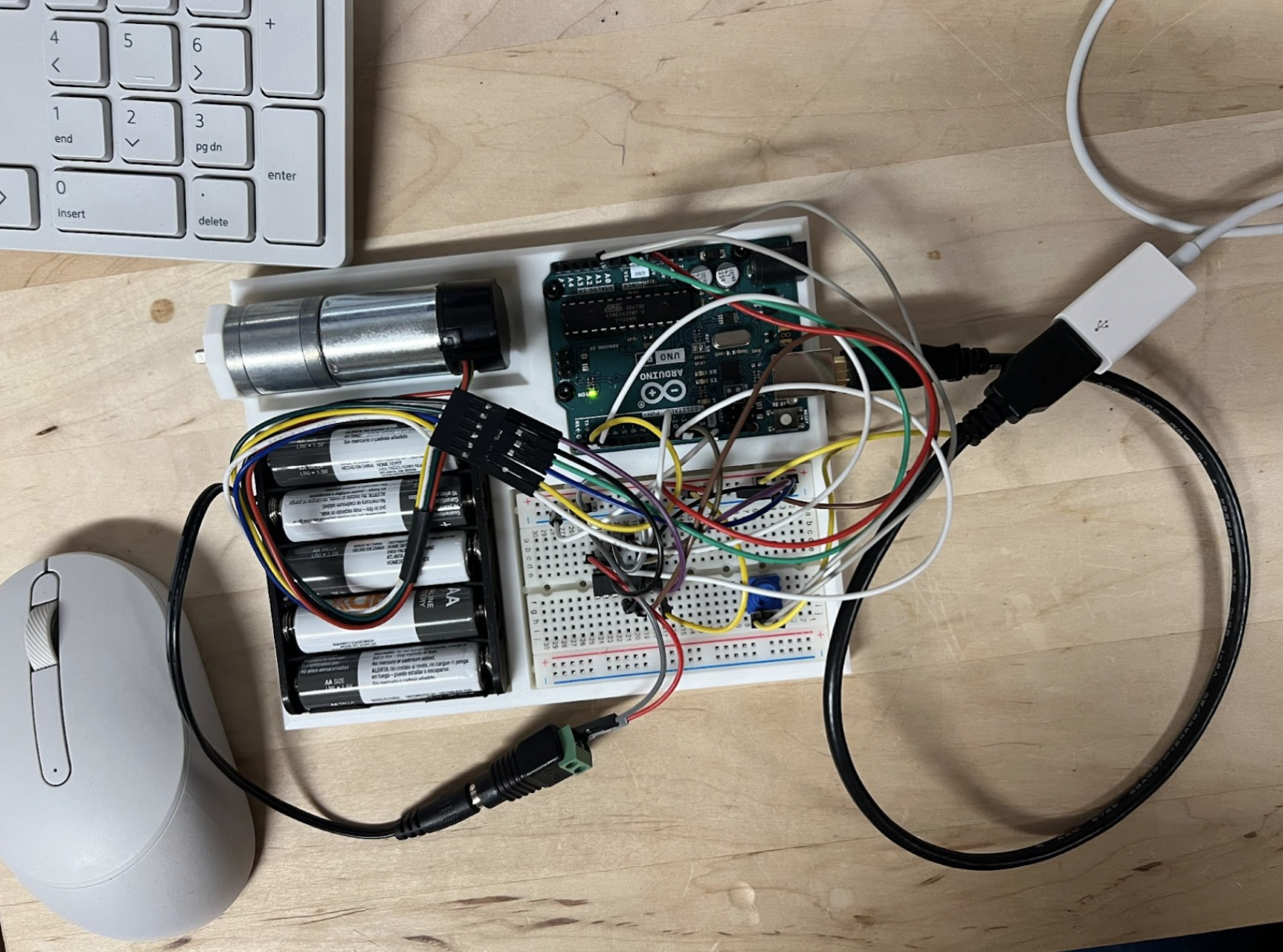
Hardware setup showing Arduino, DC motor with encoder, H-bridge, and potentiometer for real-time control
Key Objectives:
- Position control using cascaded PID architecture with potentiometer reference input
- Speed control using PI controller with encoder feedback
- Comparative analysis between simulation and hardware performance
System Modeling
Developed comprehensive mathematical models of the DC motor system:
Transfer Function Approach:
- Derived motor dynamics relating input voltage to angular velocity
- Simplified first-order system: TF = K/(τs+1)
- Calculated system parameters: DC gain K, time constant τ, viscous friction coefficient b
System Parameters:
- Motor inertia (J): 0.00976 kg·m²
- Resistance (R): 5 Ω
- Torque constant (Kt): 1.119 Nm/A
- Back-EMF constant (Kb): 0.00953 V·s
- No-load speed: 35 RPM at 6V
Part 1: Position Control
Control Architecture
Cascaded PID Design:
- Inner loop: Stabilizes pendulum angle
- Outer loop: Tracks cart position reference
- Reference input: Potentiometer mapped 0-360°
- Feedback: Encoder readings
- Actuator: H-bridge with bidirectional control (max 40N)
Controller Tuning Process
Iteratively tested proportional gains to optimize performance:
- Kp = 0.7: Insufficient tracking, large steady-state error
- Kp = 3.5: Improved response, still lagged on small changes
- Kp = 7: Optimal performance (selected)
Performance Results
| Metric | Hardware | Simscape |
|---|---|---|
| Avg Settling Time | 1.89s | ~35s |
| Avg Steady-State Error | 2.05° | 0° (theoretical) |
| Overshoot Range | 8.20-13.2% | 41.1-57.0% |
| Max Overshoot | 13.2% (0° ref) | 57.0% (0° ref) |
Key Finding: Hardware achieved 18.5× faster settling than simulation, with lower overshoot but slight steady-state error due to friction and real-world dynamics.
Part 2: Speed Control
Control Architecture
PI Controller Design:
- Reference input: Potentiometer (5 test speeds: 4.93 to 25.51 RPM)
- Feedback: Encoder-based speed measurement
- Control: PWM output via H-bridge
- Tuning: Kp = 1.5, Ki = 1.0 (manual iterative tuning)
Performance Comparison
Time to 90% of Reference Speed:
| Reference (RPM) | Simscape (s) | Hardware (s) |
|---|---|---|
| 4.927 | 0.577 | 0.042 |
| 10.000 | 0.939 | 0.042 |
| 15.015 | 1.627 | 0.125 |
| 19.853 | 2.447 | 0.167 |
| 25.513 | 3.812 | 0.250 |
Overshoot Percentage:
| Reference (RPM) | Simscape (%) | Hardware (%) |
|---|---|---|
| 4.927 | 8.33 | 11.11 |
| 10.000 | 17.17 | 8.33 |
| 15.015 | 29.33 | 18.18 |
| 19.853 | 33.50 | 18.18 |
| 25.513 | 20.08 | 12.00 |
Key Trends:
- Hardware consistently faster response times (up to 15× faster at high speeds)
- More controlled overshoot in hardware (8-18%) vs simulation (8-33%)
- Natural damping from friction, gear resistance, and mechanical inertia stabilized real-world response
Key Insights
Simulation vs Hardware Discrepancies
Why Hardware Outperformed:
- Real-world friction and damping effects not fully captured in Simscape
- Older H-bridge model in simulation doesn’t match actual switching dynamics
- Encoder noise, wiring resistance, and mechanical play provide natural stabilization
- PWM characteristics differ between simulated and physical systems
Validation: Both systems showed consistent trends: higher reference speeds require greater control effort and longer response times, confirming PI controller effectiveness across platforms.
Technical Skills Demonstrated
- Control Theory: PID/PI tuning, cascaded control loops, feedback systems
- Modeling: Transfer functions, state-space representation, Simscape multibody dynamics
- Hardware Integration: Arduino programming, encoder interfacing, H-bridge motor control, PWM generation
- Analysis: Performance metrics (settling time, overshoot, steady-state error), comparative evaluation
- Tools: MATLAB/Simulink, Simscape, real-time target execution
Challenges & Solutions
Challenge: Encoder noise at low speeds causing unstable feedback
Solution: Implemented signal smoothing and filtering
Challenge: Potentiometer-to-RPM scaling mismatch
Solution: Developed conversion factor (360/1018 for position, custom mapping for speed)
Challenge: PI gains causing instability in initial tests
Solution: Iterative manual tuning balancing response speed and overshoot
Challenge: Intermittent PWM signal dropouts
Solution: Identified and secured loose wiring connections
Challenge: H-bridge direction control logic errors
Solution: Revised switching logic for consistent bidirectional operation
Conclusion
Successfully implemented and validated closed-loop position and speed control for a DC motor system. Hardware implementation demonstrated superior response characteristics compared to simulation, highlighting the importance of real-world testing. The project confirmed that while Simscape provides valuable design insights, physical validation reveals system behaviors—natural damping, friction, and unmodeled dynamics—that significantly improve practical performance.