Differential End Cap - Manual Lathe Machining
Overview
Machined a custom differential end cap for the Northeastern Mars Rover using a manual Clausing lathe. The project required multiple operations including turning, facing, grooving, drilling, and tapping, with critical attention to dimensional accuracy and workholding strategies for a challenging cylindrical geometry.
Key Challenge: Execute a complex multi-operation sequence on a manual lathe while managing limited workholding, maintaining concentricity across operations, and converting metric specifications to imperial measurements.
Project Setup & Planning
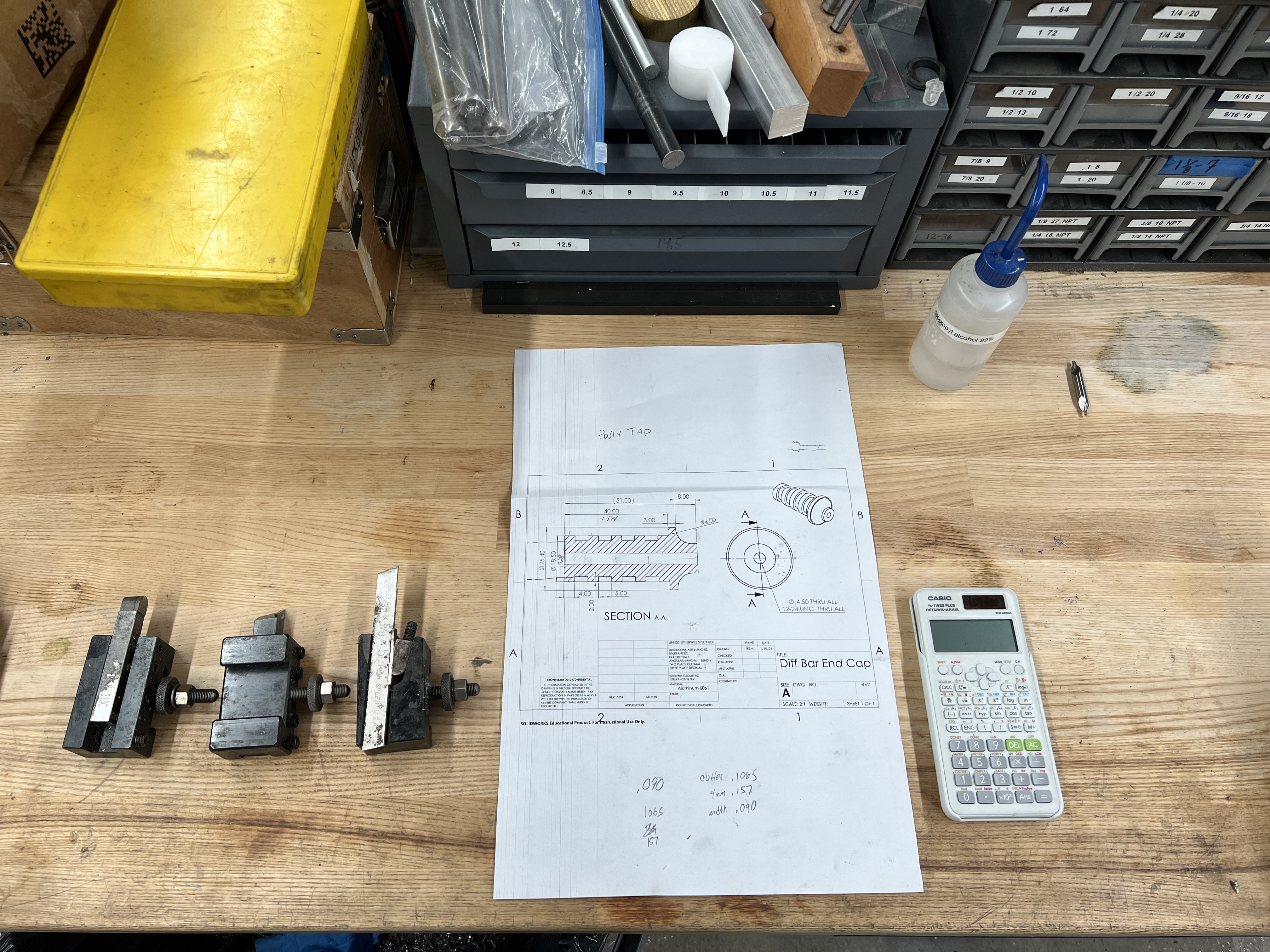
Technical drawing with cross-sections, three tool holders, calculator for unit conversion, and organized tooling.
Part Requirements
- Application: Differential end cap for Mars Rover drivetrain
- Material: Aluminum 6061-T6
- Key Features: Multiple grooves (likely for O-rings/snap rings), internal threads, precise outer diameter with flange
- Drawing Format: Metric dimensions requiring conversion to imperial for machine operation
Tooling Strategy
The project required three primary tool types:
- Turning tool - Reduce outer diameter to specification
- Facing tool - Create perpendicular reference surfaces
- Grooving tool - Cut retention grooves in the part body
Machine: Clausing manual lathe with 3-jaw chuck, tailstock, and dial indicator capabilities
Unit Conversion Challenge
The technical drawing provided metric dimensions, but the Clausing lathe uses imperial (inch) graduations on all handwheels and dials.
Process:
- Converted all critical dimensions from mm to inches before starting
- Calculated decimal inch values for diameter, groove depths, and lengths
- Referenced conversion throughout machining to ensure accuracy
Key Learning: Always verify unit systems between drawings and machine tools. Having a conversion reference readily available prevented dimensional errors during operation.
Operation 1: Facing
Facing operation: Establishing the perpendicular reference surface before turning to diameter. Note the clean aluminum chips and cutting fluid application.
Establishing the Reference Surface
Started by facing the end of the stock to create a clean, perpendicular reference surface. This operation is critical because all subsequent measurements and operations reference from this faced surface.
Setup:
- Mounted stock in 3-jaw chuck with minimal overhang
- Installed facing tool in tool post
- Applied cutting fluid to improve surface finish
Result: Clean, flat surface perpendicular to the rotation axis, ready for diameter turning operations.
Operation 2: Turning to Diameter
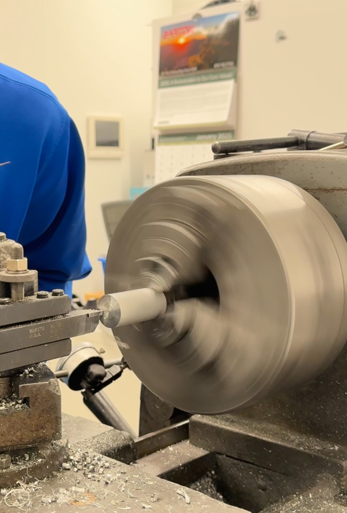
Turning to diameter: Taking 0.030" cuts with cutting fluid to prevent chatter marks. The smooth surface finish demonstrates proper cutting parameters.
The “Creeping Up” Technique
Critical Learning: You cannot turn directly to final diameter on a manual lathe. Tool deflection, material spring-back, and machine backlash mean you must approach the target dimension incrementally.
Process:
- Rough cuts: Take 0.030” (30 thou) per pass to remove bulk material
- Measure frequently: Use micrometer screw gauge after each pass
- Creep up: As you approach final dimension, reduce cut depth
- Establish zero reference: Once at dimension, note the dial setting for consistent results
Cutting Parameters:
- Depth of cut: 0.030” per pass (rough), reducing to 0.005-0.010” near final dimension
- Applied cutting fluid continuously to prevent chatter marks and improve surface finish
Preventing Chatter
Problem: Without cutting fluid, the tool can vibrate (chatter), leaving spiral marks on the surface and potentially breaking the tool.
Solution: Continuous application of cutting fluid provides:
- Lubrication between tool and workpiece
- Heat dissipation from cutting zone
- Improved surface finish
- Extended tool life
Result: Smooth, chatter-free surface finish on the turned diameter.
Operation 3: Grooving
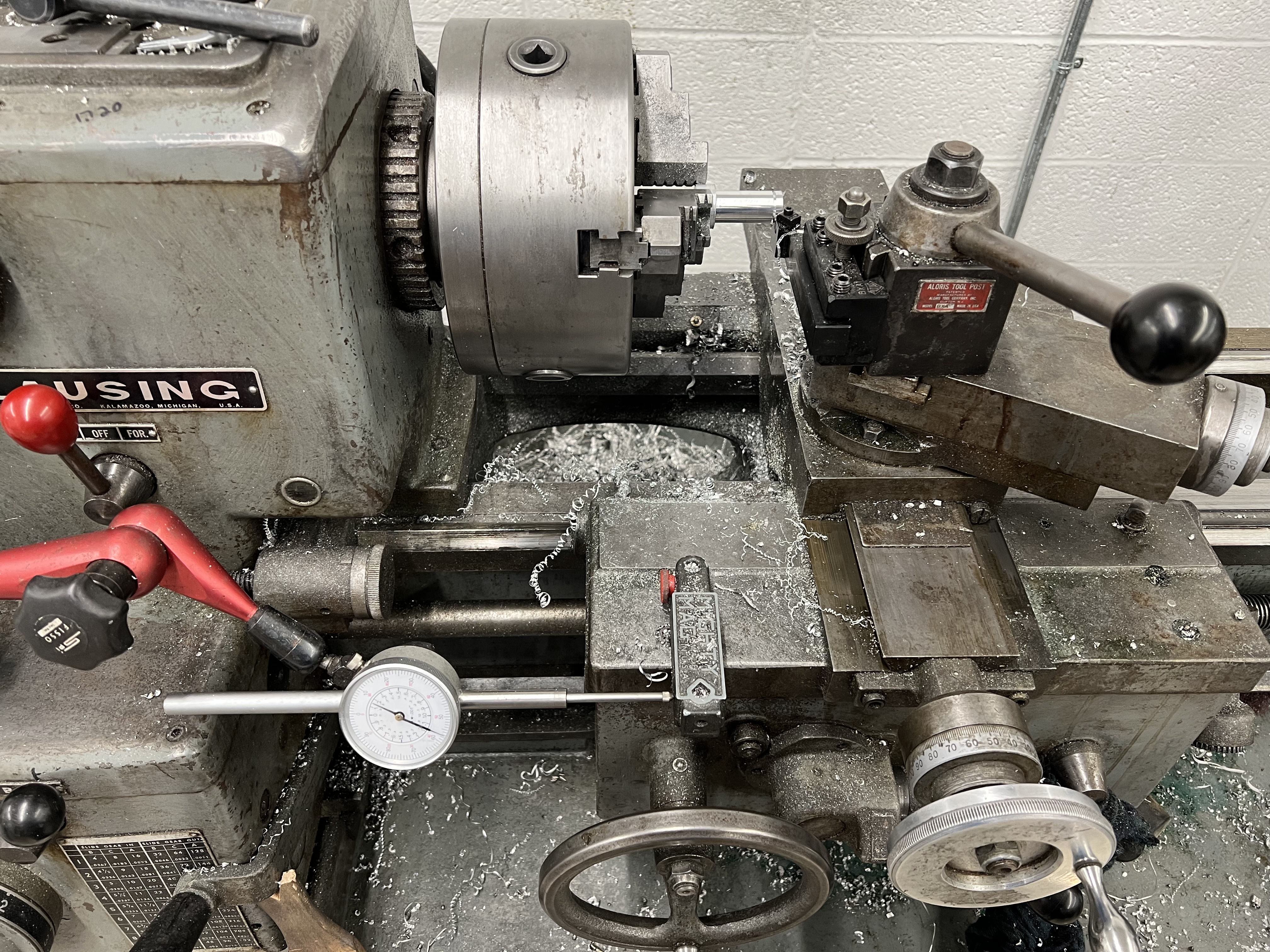
Grooving operation on Clausing lathe: Short, stubby grooving tool provides rigidity. Dial indicator mounted on carriage tracks depth precisely.
Tool Rigidity Matters
Initial Attempt: Started with a longer grooving tool holder for ease of setup.
Problem: The tool “walked” - chattering and deflecting during the cut due to excessive overhang creating a lack of rigidity.
Solution: Switched to a short, stubby grooving tool holder with minimal overhang. The shorter tool provided much better rigidity and prevented deflection.
Key Indicators of Success:
- Curly, continuous chips (sign of sharp tool and proper cutting action)
- No chatter or vibration
- Clean groove walls
Workholding Constraint
Challenge: Limited material extending from the chuck jaws meant minimal clamping surface. Too much force from cutting could dislodge the workpiece.
Adaptation:
- Took lighter cuts than normal
- Reduced feed rate
- Used step-up approach: multiple shallow passes rather than one deep cut
- Monitored part security constantly
Process: Referenced the technical schematic for groove depth, used dial indicator mounted on carriage to precisely control depth of each grooving pass.
Groove Width Verification
Quality Control Technique: To ensure consistency and accuracy of groove widths, we used a drill shank slightly under the specified groove width as a gauge.
Method:
- After cutting each groove, test-fit a drill shank into the groove
- The shank diameter was selected to be slightly smaller than the target groove width
- If the shank fits smoothly, the groove width meets minimum specification
- This provided immediate go/no-go verification without removing the part from the chuck
Why This Works: Using a physical gauge provides instant feedback during machining rather than waiting until the part is complete. The drill shank acts as a precision reference that’s readily available in any shop, making it practical for quick verification between passes.
Operation 4: Center Drilling
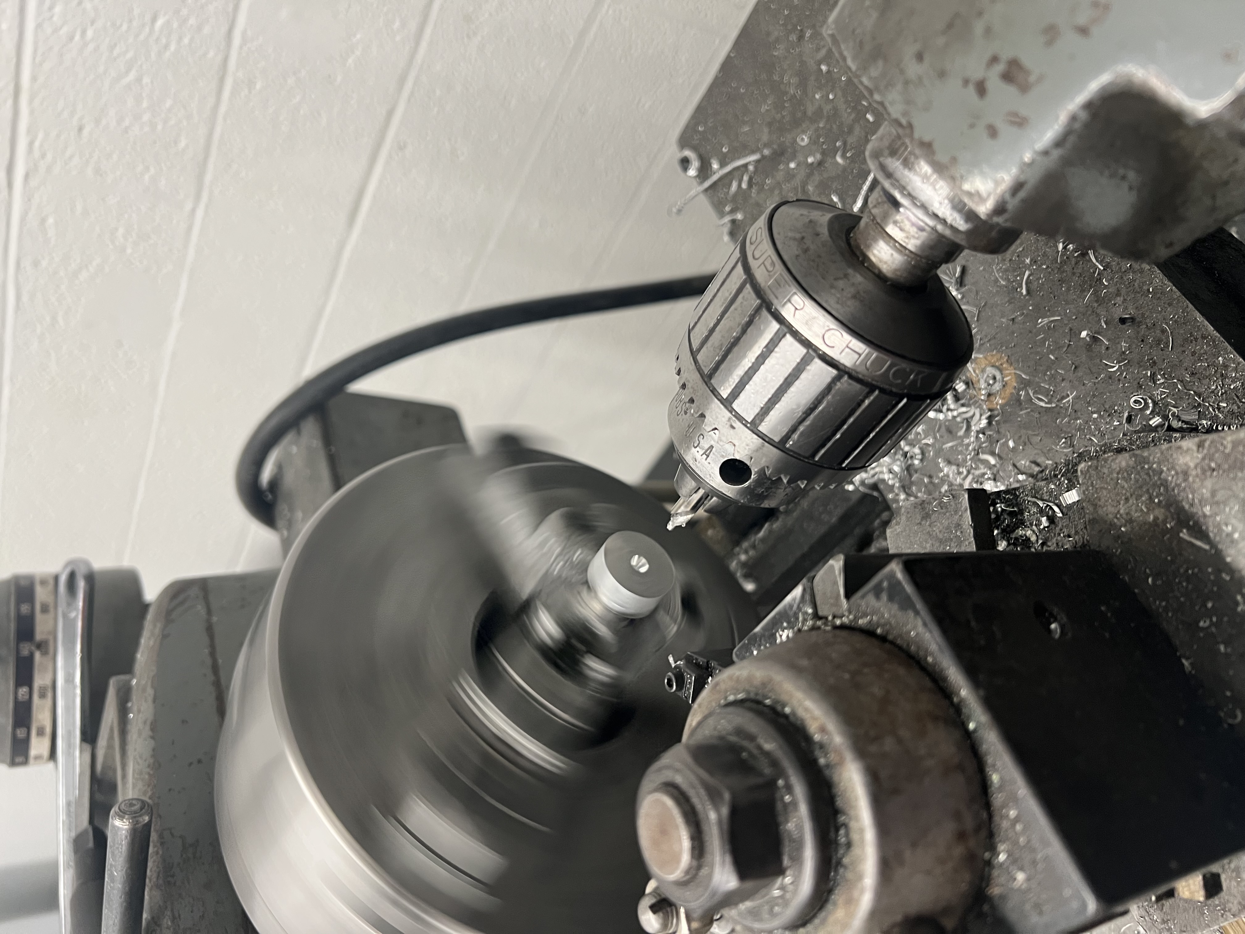
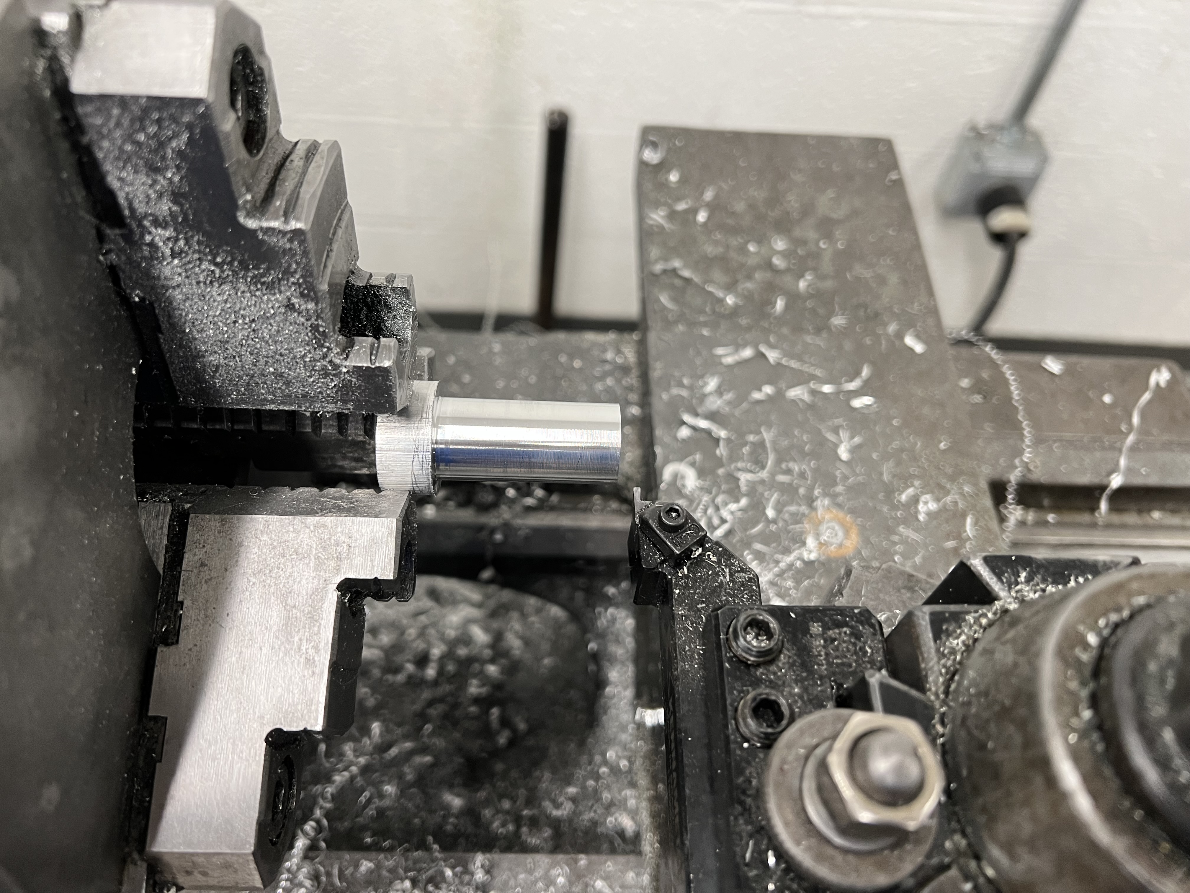
Center drilling: Short, stubby center drill in tailstock chuck creates precise starting point. The finished part shows visible grooves machined in previous operations.
Why Center Drill First?
The Problem on a Lathe: On a lathe, the drill bit is stationary (held in tailstock) while the workpiece rotates. Regular twist drills tend to “walk” or wander off-center when starting on a rotating surface.
The Solution: Center drills are short and stubby, making them extremely rigid. They don’t walk off-center and create a precise starting point for subsequent drilling operations.
Process:
- Mount center drill in tailstock chuck
- Advance tailstock to engage part
- Create center dimple exactly on axis of rotation
- This pilot hole guides the twist drill perfectly on-center
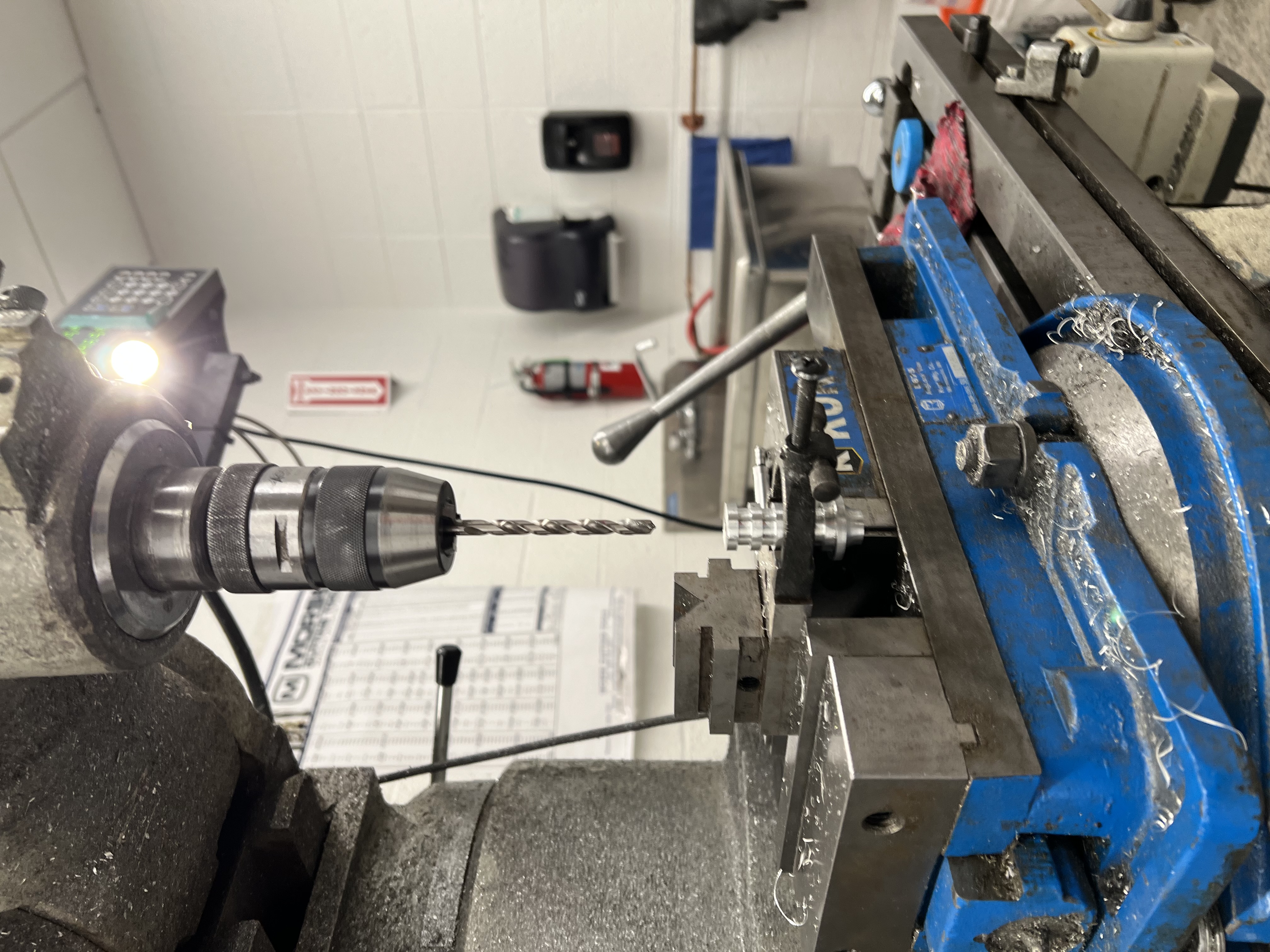
Operation 5: Drilling
After center drilling created the starting point, followed with the appropriate diameter twist drill to create the through-hole (or partial depth hole) for the threaded portion.
Setup: Drill held in tailstock chuck, advanced using tailstock handwheel for controlled feed rate.
Operation 6: Tapping - Maintaining Concentricity
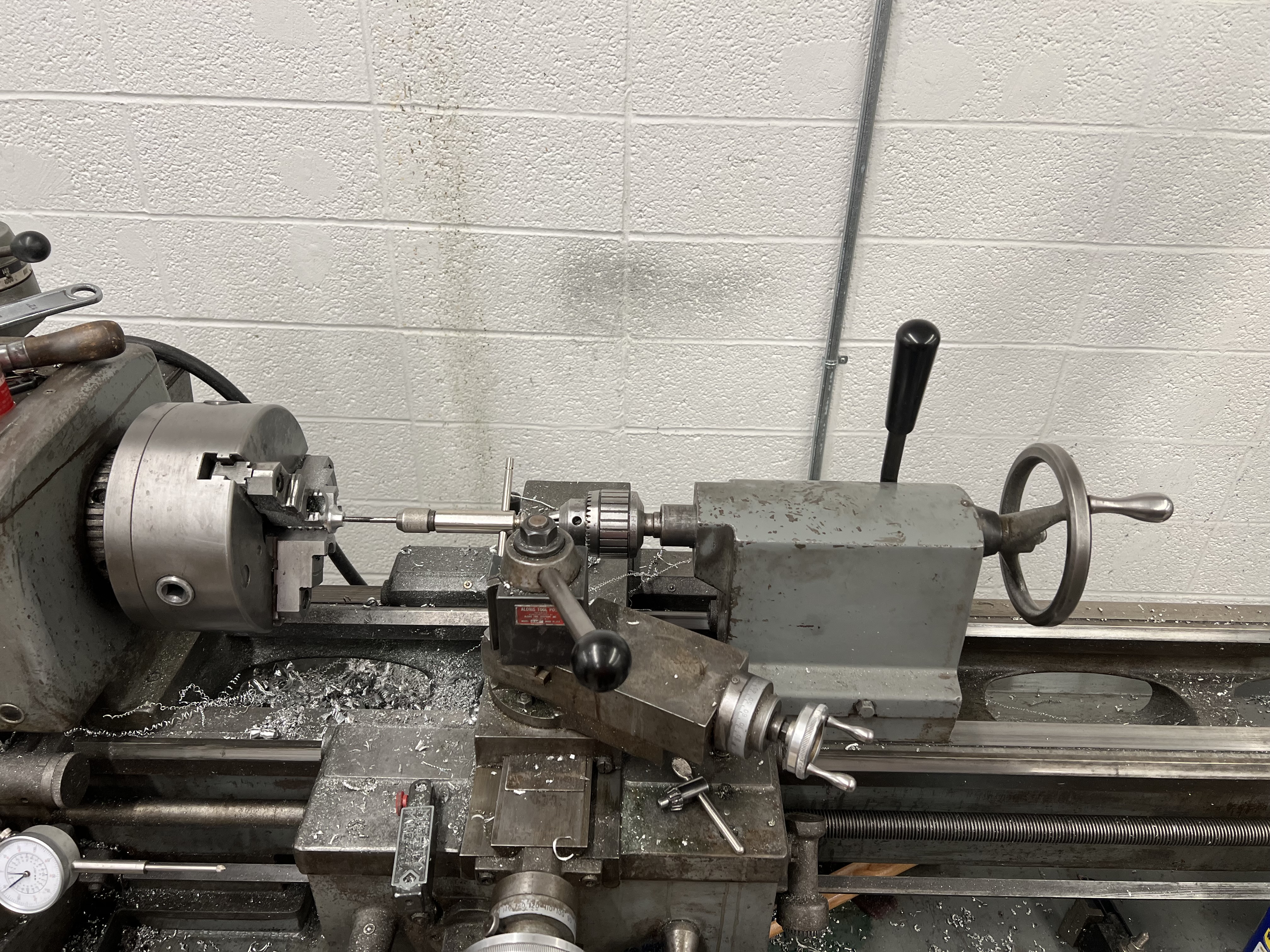
Tailstock tapping: Tap held in tailstock chuck maintains perfect alignment with rotation axis, ensuring concentric threads with turned features.
Tailstock Tapping Technique
Why This Method: Holding the tap in the tailstock chuck ensures the tap stays perfectly aligned with the lathe’s centerline. This creates threads that are perfectly concentric with the turned outer diameter.
Process:
- Install tap in tailstock chuck
- Workpiece rotates (powered by lathe)
- Manually feed tap using tailstock handwheel
- Back out periodically to clear chips
- Apply tapping fluid for lubrication
Problem Encountered: The tap wasn’t long enough (not an extension tap) to reach all the way through the part from one end.
Solution Required: Need to complete the operation from the opposite end on the mill.
Precision Measurement Techniques
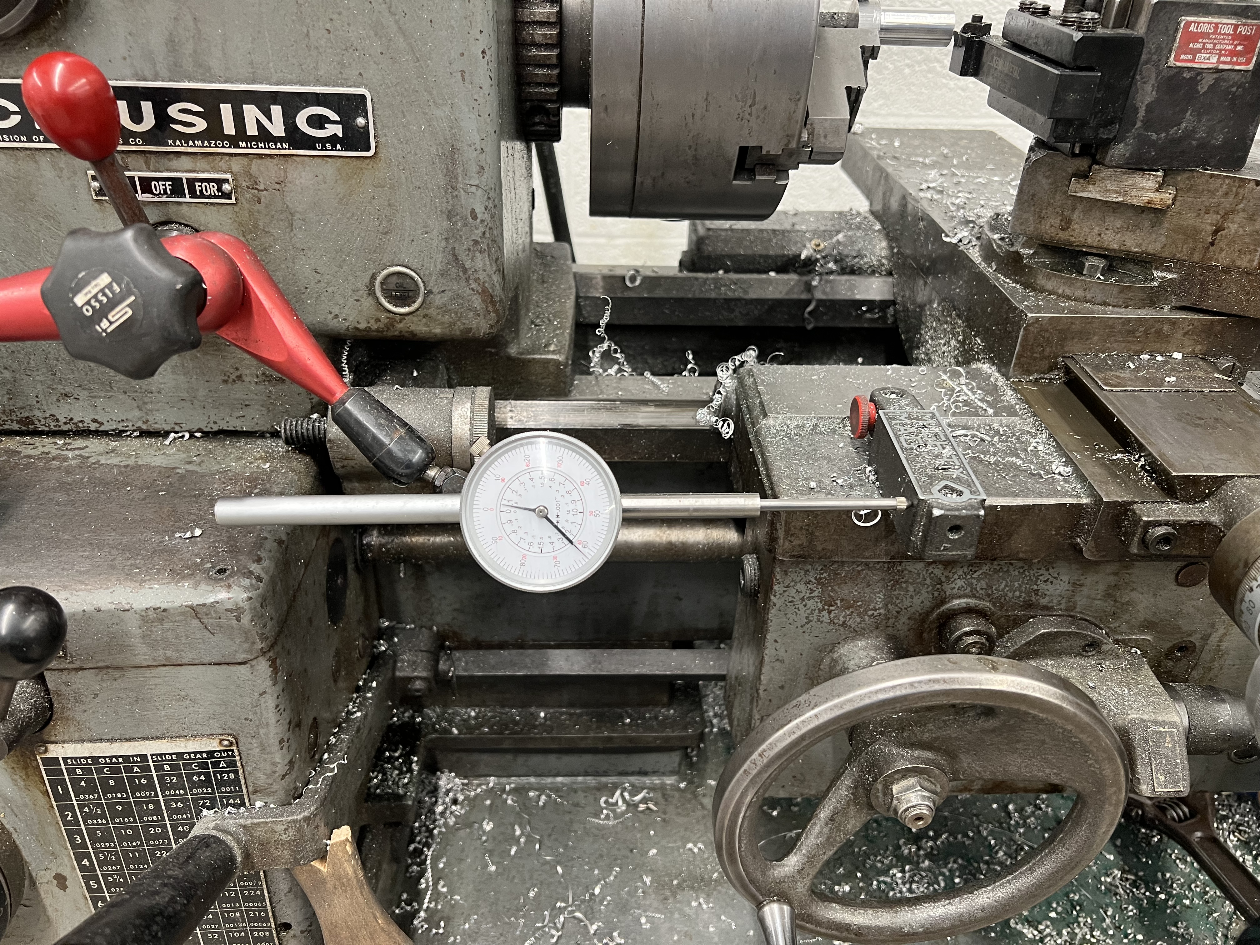
Precision measurement: Dial indicator mounted on carriage provides accurate depth control independent of handwheel backlash.
Dial Indicators for Two-Axis Control
Carriage-Mounted Dial Indicator:
- Measured depth of cuts
- Tracked groove depths
- Verified facing operations
Tool Post Dials/Graduations:
- Controlled lateral movement (cross-feed)
- Set precise diameters
- Repeated consistent dimensions
Why This Matters: Dial indicators provide precise, repeatable measurements independent of machine backlash. The handwheel graduations alone can be inaccurate due to wear and backlash in the lead screw.
Technique: Zero the indicator at a known reference point, then read directly how far the tool has moved - much more reliable than counting handwheel marks.
Operation 7: V-Block Fixturing on Milling Machine
V-block fixturing on milling machine: Completing operations on the flanged end where the lathe chuck couldn't grip adequately.
The Flange Workholding Challenge
The Problem: After completing the main body operations on the lathe, we needed to machine features on the opposite end of the part - the flanged section. However, the flange geometry created a critical workholding problem:
- Insufficient stock for lathe chuck: The flange was too thin and wide to grip securely in the 3-jaw chuck
- Risk of part damage: Attempting to clamp on the finished grooved section would mar the precision surfaces
- No reference surface: The flanged end needed to remain accessible for drilling/tapping operations
Why the Lathe Wouldn’t Work: With most of the part already machined to final dimensions and the flange geometry preventing secure clamping, there simply wasn’t enough stock material left to hold the part safely in the lathe chuck. Any attempt to grip the thin flange would either:
- Deform the part from clamping pressure
- Provide insufficient holding force, risking the part coming loose during cutting
- Damage the already-finished surfaces
Solution: V-Block Fixturing on the Mill
The V-Block Advantage: V-blocks are specifically designed to hold cylindrical and flanged parts by:
- Self-centering: The 90-degree V-groove automatically centers round stock on the part’s axis
- Full-length support: The entire body of the part rests in the V, distributing clamping forces
- No marring: Clamping happens across the sides, not on finished surfaces
- Accessibility: The flanged end remains fully accessible for drilling, tapping, and facing operations
Setup Process:
- Placed the finished part in the V-block with the cylindrical body seated in the V-groove
- Aligned the part axis with the mill spindle using a dial indicator
- Clamped the V-block securely to the mill table (blue vise visible in setup)
- Verified alignment before beginning operations
- Completed drilling, tapping, and any final facing operations on the flanged end
Operations Completed on Mill:
- Drilling through-hole from opposite end (tap was too short from first side)
- Threading operations if needed
- Any additional features on the flange face
Key Takeaway: Adaptive Workholding
This demonstrates a critical skill in manual machining: knowing when to transition between machines based on workholding constraints. The lathe excelled for the main turning, facing, and grooving operations where we had adequate stock to grip. But when the geometry changed and holding stock became limited, moving to the mill with V-block fixturing was the right solution.
Problem-Solving Checklist:
- ✓ Recognized workholding limitation before it became a safety issue
- ✓ Selected appropriate alternative fixturing method (V-blocks)
- ✓ Chose correct machine for remaining operations (mill vs. lathe)
- ✓ Maintained part quality throughout the process
- ✓ Completed all required features despite initial limitations
Final Result
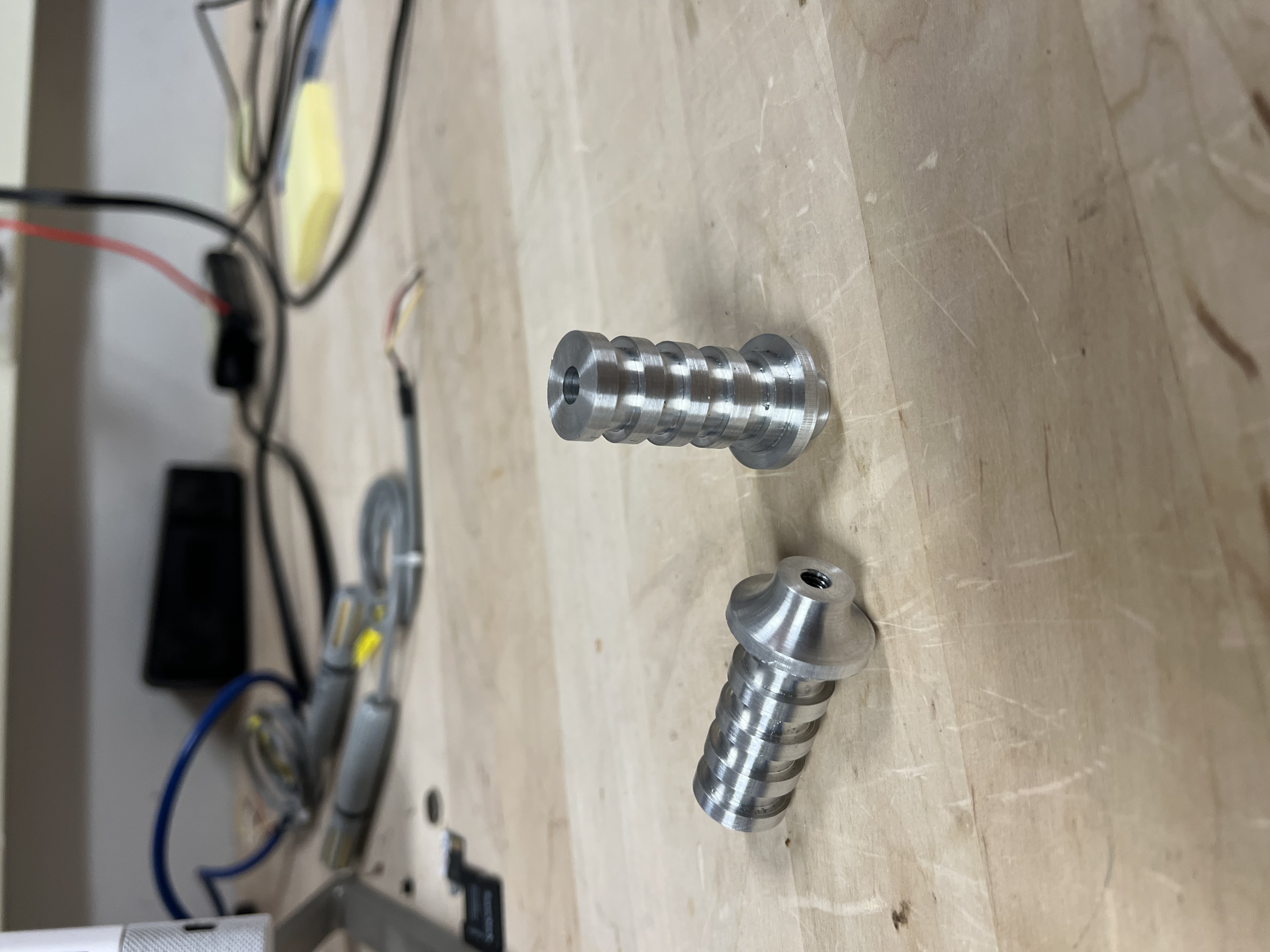
Finished parts: Two completed differential end caps showing clean grooves, threaded holes, and excellent surface finish throughout all machined features.
Complete Operation Sequence
- Facing - Clean up end face to establish perpendicular reference
- Turning - Reduce diameter in 0.030” increments, creeping up to final dimension
- Grooving - Cut retention grooves (switched to short tool for rigidity)
- Center Drilling - Create precise starting point for drilling
- Drilling - Drill to depth from first end
- Tapping (Lathe) - Cut threads maintaining concentricity
- V-Block Fixturing (Mill) - Complete operations on flange end where lathe chuck couldn’t grip
Key Learnings
Manual Machining Fundamentals
“Creeping Up” Technique: Never dial directly to final dimension. Material spring-back, tool deflection, and machine backlash mean you must approach the target incrementally while measuring frequently.
Tool Rigidity is Critical: Longer tools deflect more. When experiencing chatter or “walking,” switch to shorter, stubbier tooling for better rigidity - especially important for grooving operations.
Cutting Fluid Prevents Chatter: Continuous application of cutting fluid reduces friction, dissipates heat, and prevents vibration that causes chatter marks on the surface.
Workholding Strategy
Know When to Change Machines: The flange geometry and limited remaining stock made continued lathe work impossible. Recognizing this limitation early and transitioning to V-block fixturing on the mill prevented part damage and maintained quality.
V-Blocks for Complex Geometries: When cylindrical parts have flanges, steps, or features that prevent conventional chuck gripping, V-blocks provide secure, self-centering workholding without damaging finished surfaces.
Plan for Workholding Throughout the Process: Consider how you’ll hold the part at each stage. What’s easy to grip at the beginning may become impossible as you remove material and add features.
Lathe-Specific Techniques
Center Drilling on Lathe: The drill is stationary while work rotates - opposite of a drill press. Short, stubby center drills prevent walking and create accurate starting points.
Tailstock Tapping for Concentricity: Holding the tap in the tailstock maintains perfect alignment with the rotation axis, ensuring threads are concentric with turned features.
Dial Indicators Over Handwheels: Use dial indicators for precision measurement rather than relying solely on handwheel graduations which suffer from backlash.
Quality Control
In-Process Verification: Using drill shanks as go/no-go gauges for groove widths provides immediate feedback during machining, preventing scrapped parts from dimensional errors discovered too late.
Unit Conversion
Metric to Imperial: Always verify drawing units against machine units. Convert all critical dimensions before starting operations and keep conversion references handy.
Results & Evaluation
Dimensional Accuracy: Successfully achieved all specified dimensions within tolerance by using the creeping-up technique and frequent micrometer measurements.
Concentricity: Tailstock tapping and center drilling maintained excellent concentricity between threaded features and turned diameters.
Surface Finish: Cutting fluid application resulted in smooth, chatter-free surfaces on all turned and faced features.
Workholding Solutions: V-block fixturing on the mill successfully completed operations on the flange end after the lathe chuck could no longer grip the part securely.
Problem-Solving: Switching grooving tools when the long tool walked, and transitioning to the mill for flange operations demonstrated good troubleshooting and adaptive thinking.
Quality Assurance: Drill shank groove verification ensured dimensional consistency across all grooves without requiring part removal.
Technical Skills Demonstrated
- Manual Lathe Operation: Turning, facing, grooving, drilling, tapping on Clausing lathe
- Milling Machine Operation: V-block setup, alignment, drilling operations
- Precision Measurement: Micrometer, dial indicator, caliper usage
- Workholding: 3-jaw chuck setup, V-block fixturing, managing limited clamping surface, recognizing workholding constraints
- Tool Selection: Choosing appropriate tooling for rigidity and operation type
- Process Planning: Multi-operation sequencing, identifying machine limitations, transitioning between machines
- Problem Solving: Adapting to flange geometry constraints, limited stock challenges, tool length limitations
- Unit Conversion: Metric to imperial conversion for dimensional accuracy
- Quality Control: In-process verification, go/no-go gauging techniques